Now you can hopefully see why these optomechanics systems are so fun. Once I finished building, part of me wanted to break the whole thing down and start over. Just like I did with my LEGOs when I was a kid.
Wednesday, December 28, 2011
Optomechanics Are Rad - Part II
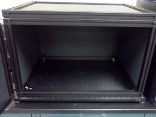
In my last installment, I described the construction of a dip-coating apparatus for applying thin films onto the tips of optical fibers. With that out of the way, the next step involved the construction of an optics system for measuring the fluorescence produced by a thin film on the tip of an optical fiber. And so that's what I set about doing today. Similarly to the dip-coater, I started with a clean breadboard. Because I am measuring fluorescence with this system, I wanted to minimize any stray light, so I enclosed the breadboard within a black box. The box is hinged in such a way that the top and front can be opened.
Inside the box, I put my detector - a handheld spectrometer (left) - and my light source - a blue laser (right). Not shown is the laser's power supply. This unit is somewhat bulky and, since it doesn't necessarily need to be inside the box, I left it out. By the way, I apologize for the blurriness of these images; this is the product of a mediocre phone camera combined with shaky hands brought on by a bit too much morning coffee.
I decided that I would take all of my measurements by submerging the fiber tip into a fluid sample, into which I could then inject the analyte that I'm trying to detect and thus monitor any change in the fluorescence output in real time. I also wanted to illuminate the fiber tip with the laser transversely - or perpendicular to the direction of the fiber - by slicing the laser's coherent beam directly across the tip of the fiber to maximize my excitation intensity. In order for all this to work correctly, I decided to use a cuvette to hold the sample, therefore minimizing scattering as the beam enters the liquid sample. So I put a cuvette holder into the box and secured it in place using a few breadboard mounts. Then I aligned the laser so that the beam was directed through the center of the cuvette holder and bolted it into place.
With the cuvette holder and laser aligned and anchored onto the breadboard, I then needed some way of holding the fiber in place. In order to make sure that each fiber could be accurately positioned into the path of the laser, I bolted two micro-manipulators onto the breadboard to act as the base of the fiber holder while also allowing me to adjust the X and Y position of the fiber.
Onto the micro-manipulators I then added a fiber holder. The fiber holder seen in this image came more-or-less preassembled. The lower section has a turnscrew that clamps the fiber in place and I added the tube seen in the upper section to help keep the fiber straight as it enters the cuvette. Astute observers might notice that the fiber holder I've used is manufactured by Newport, whereas pretty much every other optomechanic component I've used is manufactured by ThorLabs. What can I say? The Newport fiber holder was all I had on hand. It was a bit of a pain in the ass getting it secured to the ThorLabs components because the dimensions and threading are different between the two manufacturers, but I got things worked out nonetheless. And once the fiber holder was in place, the whole thing was finished.
To test the system out, I popped an empty cuvette into the cuvette holder and threaded a fiber through the fiber holder and down into the cuvette. I attached the other fiber terminus - the one with the SMA connector - to the spectrometer and turned on the laser. Then I used the micromanipulators to position the fiber tip directly into the beam of the laser. You can see in the picture below that once the laser was incident onto the fiber, the blue laser light was scattered everywhere and fiber tip seemed to glow bright blue.
If there were a thin layer of my novel fluorescence sensor material on the tip of the optical fiber, which there is not because this was just a spare fiber that I found lying around, it would emit a bright green fluorescence when excited by the laser. The fluorescence emission would be guided through the fiber and into the spectrometer. The spectrometer is connected via USB to a laptop computer equipped with software that shows the real-time fluorescence spectrum being sent through the fiber. And there you have it. Pretty easy to set up and use. By using a coherent light source along with a fluorescent sensor material coated directly onto an optical fiber, I've negated the need for lenses or other optics. Once you start adding lenses, alignment becomes a major issue, and the components have to be aligned and adjusted precisely. On the other hand, this system required only minimal alignment and went from a clean breadboard to a fully functional optical measurement system with about 2 hours of build time.
Now you can hopefully see why these optomechanics systems are so fun. Once I finished building, part of me wanted to break the whole thing down and start over. Just like I did with my LEGOs when I was a kid.
Now you can hopefully see why these optomechanics systems are so fun. Once I finished building, part of me wanted to break the whole thing down and start over. Just like I did with my LEGOs when I was a kid.
Subscribe to:
Post Comments (Atom)


No comments:
Post a Comment